Hoople
Account Removed
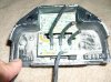
More useless information from the desk of Hoople! Some may find it interesting as to what is really inside a Black Box HD regulator so here goes. My Thanks go out to Rich (rjsogard) who contacted me and donated the DOA organ to research.
The Regulator is an HD part # 74631-06 black box. I don't have the published current specs on this regulator but I believe it is rated at 38 amps. After de-potting the unit I was able to identify the vender & designer to be Tympanium Corporation out of Malden MA 02148 (Charge Indicators, Regulators & Ignition Modules for Small Engines from Tympanium Corporation).
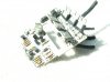
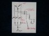
The reversed schematic I was able to come up with is broken down into 2 free hand pages. Note that the unit (as expected) contains real no filtering or smoothing of ripple content. The battery in this case is the primary ripple filter. Sheet 1 is the business end of the regulator which is responsible for all the heavy current switching. Six components are primarily responsible for controlling and directing the 3 outputs of the stator. I would guess 75% of all failed regulators are probably the result of 1 of these 6 following components going shorted.
(3X) 2n6507 (25 amp@ 400v) SCR by ON Semiconductor Corp.
(3X) FES16GT (16amp@400v) TO220 Rectifier.
Note: The tabs of the SCR'S (Anode) are machine screw to frame ground.
The Tabs on the Rectifiers were isolated but heatsinked.
Remember unlike an automotive alternator that has an electromagnet field winding, HD alternators are Permanent Magnet. That changes the entire landscape of regulator design. Instead of regulating the output of the alternator by increasing or decreasing the strength of the field winding as is done in an automotive alternator, output regulation is done by controlling the gates of the SCR's since the field in our case is a fixed strength permanent magnet. Sheet 2 is the regulation circuits of the entire regulator. Note that the sole responsibility of page 2 is to control the gates of the SCR's. The entire regulator was made up entirely of discrete components. Not one integrated circuit (multi pin dip) was used. I do like what I saw. It was nicely made & looked to represent a fair price for what it contained and on top of that it appeared to be US made.
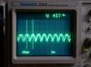
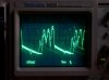
I also included 2 waveform pictures from my ’09 Dyna to show what a baseline view of ripple will be at idle and also what the wave looks like when the regulator starts kicking in to limit (or regulate) the charging voltage. In the 1st scope picture you can clearly see the ripple frequency was 475 Hz/sec. That number is correct because since there are 3 phases to the stator and there are 6 rotor magnets, each revolution of the crank shaft will yield 18 voltage crests. Now multiply 18 by the RPM of the engine (1575 RPM), and dividing by 60 (60 seconds/min) will give you the frequency of the voltage ripple, which in this case was 475/sec. If something was wrong with 1 of those SCRs or Diodes mentioned above, that frequency would not be correct at the RPM under test.
Keep this in mind if your really trying to see if your regulator is bad. If you see the correct number of "crests" with no gaps, at least you know all 3 phases are making their way to your battery.
Scope picture 2 shows the regulator turning off the SCR’s thereby limiting the stator output from overcharging the battery. That will be the voided time period when the ripple appears to be missing. This is the action you will see when the regulator is doing its job and is limiting the charge going to the battery. This is totally unlike what you will see with electromagnetic field magnets (rotors) as found in automobiles. (The double images you see in both scope pictures were caused by the long shutter speed of the camera without using a flash & not due to lack of proper scope sync)
Just having some Fun so if you see any brutal mistakes, plz be easy on me. Hope you found it interesting.
Hoop!
The Regulator is an HD part # 74631-06 black box. I don't have the published current specs on this regulator but I believe it is rated at 38 amps. After de-potting the unit I was able to identify the vender & designer to be Tympanium Corporation out of Malden MA 02148 (Charge Indicators, Regulators & Ignition Modules for Small Engines from Tympanium Corporation).
The reversed schematic I was able to come up with is broken down into 2 free hand pages. Note that the unit (as expected) contains real no filtering or smoothing of ripple content. The battery in this case is the primary ripple filter. Sheet 1 is the business end of the regulator which is responsible for all the heavy current switching. Six components are primarily responsible for controlling and directing the 3 outputs of the stator. I would guess 75% of all failed regulators are probably the result of 1 of these 6 following components going shorted.
(3X) 2n6507 (25 amp@ 400v) SCR by ON Semiconductor Corp.
(3X) FES16GT (16amp@400v) TO220 Rectifier.
Note: The tabs of the SCR'S (Anode) are machine screw to frame ground.
The Tabs on the Rectifiers were isolated but heatsinked.
Remember unlike an automotive alternator that has an electromagnet field winding, HD alternators are Permanent Magnet. That changes the entire landscape of regulator design. Instead of regulating the output of the alternator by increasing or decreasing the strength of the field winding as is done in an automotive alternator, output regulation is done by controlling the gates of the SCR's since the field in our case is a fixed strength permanent magnet. Sheet 2 is the regulation circuits of the entire regulator. Note that the sole responsibility of page 2 is to control the gates of the SCR's. The entire regulator was made up entirely of discrete components. Not one integrated circuit (multi pin dip) was used. I do like what I saw. It was nicely made & looked to represent a fair price for what it contained and on top of that it appeared to be US made.
I also included 2 waveform pictures from my ’09 Dyna to show what a baseline view of ripple will be at idle and also what the wave looks like when the regulator starts kicking in to limit (or regulate) the charging voltage. In the 1st scope picture you can clearly see the ripple frequency was 475 Hz/sec. That number is correct because since there are 3 phases to the stator and there are 6 rotor magnets, each revolution of the crank shaft will yield 18 voltage crests. Now multiply 18 by the RPM of the engine (1575 RPM), and dividing by 60 (60 seconds/min) will give you the frequency of the voltage ripple, which in this case was 475/sec. If something was wrong with 1 of those SCRs or Diodes mentioned above, that frequency would not be correct at the RPM under test.
Keep this in mind if your really trying to see if your regulator is bad. If you see the correct number of "crests" with no gaps, at least you know all 3 phases are making their way to your battery.
Scope picture 2 shows the regulator turning off the SCR’s thereby limiting the stator output from overcharging the battery. That will be the voided time period when the ripple appears to be missing. This is the action you will see when the regulator is doing its job and is limiting the charge going to the battery. This is totally unlike what you will see with electromagnetic field magnets (rotors) as found in automobiles. (The double images you see in both scope pictures were caused by the long shutter speed of the camera without using a flash & not due to lack of proper scope sync)
Just having some Fun so if you see any brutal mistakes, plz be easy on me. Hope you found it interesting.
Hoop!