
You are using an out of date browser. It may not display this or other websites correctly.
You should upgrade or use an alternative browser.
You should upgrade or use an alternative browser.
2002 road king drivetrain alignment
- Thread starter oldscoolz
- Start date
dolt
Well-Known Member
Illustration not necessary; understand completely but still not convinced that drive train alignment is causing the belt cupping. Putting that aside for the moment though, there is a down and dirty way to check/correct drive train to chassis alignment. As I mentioned in a previous post, there is a tool for that purpose; Jim's and George's Garage sells for about $400.
To properly align the bike one must loosen the front motor mount and disconnect one end of the upper and lower adjusters so that the entire assembly is relaxed. Then, with the use of the tools, the swing arm axle must be centered in the hole of the right and left side brackets. Be careful not to shove the assembly side to side, just keep it in the center. Now check the alignment of the adjusters. If the bolt holes are aligned then the bike needs no adjustment. If they are off then loosen the adjusters and move them until the bolt holes line up. The bolt should thread into its hole without resistance. Tighten everything up and that's it.
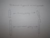
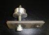
I have attached a photo of a home made tool for this purpose; you would need two of these, one for each side of the swing arm. If you have access to a machine shop, you could have these fabricated for much less than $400; I am guessing $100, all in or less. This is not my tool but one a well known engine builder made and posted the photo on another forum. The round piece (plug) started out as 1.5 inch aluminum rod. Each piece was then cut to the length of .650 inches, then machined .500 of that down to 1.245 inches leaving a .150 shoulder. The center was drilled with a lathe and threaded to 3/8. The bolt points were also cut with the lathe to assure exact centers. The plates are 3.5 inches in length and the hole centers are 1.9 inches apart. The holes are not terribly critical and can be oversized since the plate only holds the plug in place.
Once this procedure has been completed, you should check rear wheel alignment again.
To properly align the bike one must loosen the front motor mount and disconnect one end of the upper and lower adjusters so that the entire assembly is relaxed. Then, with the use of the tools, the swing arm axle must be centered in the hole of the right and left side brackets. Be careful not to shove the assembly side to side, just keep it in the center. Now check the alignment of the adjusters. If the bolt holes are aligned then the bike needs no adjustment. If they are off then loosen the adjusters and move them until the bolt holes line up. The bolt should thread into its hole without resistance. Tighten everything up and that's it.
I have attached a photo of a home made tool for this purpose; you would need two of these, one for each side of the swing arm. If you have access to a machine shop, you could have these fabricated for much less than $400; I am guessing $100, all in or less. This is not my tool but one a well known engine builder made and posted the photo on another forum. The round piece (plug) started out as 1.5 inch aluminum rod. Each piece was then cut to the length of .650 inches, then machined .500 of that down to 1.245 inches leaving a .150 shoulder. The center was drilled with a lathe and threaded to 3/8. The bolt points were also cut with the lathe to assure exact centers. The plates are 3.5 inches in length and the hole centers are 1.9 inches apart. The holes are not terribly critical and can be oversized since the plate only holds the plug in place.
Once this procedure has been completed, you should check rear wheel alignment again.
Attachments
oldscoolz
Member
very interesting, dolt. haven't seen or heard anything about that method of checking the alignment. i'm familiar with string method which i consider a down and dirty first approximation of alignment and using lasers on the brake rotors, something i've never done but seems to make good sense as long as your rotors are true.
your comments about alignment tells me that lateral deflection IS possible at the swingarm. so even though the swingarm bearings are pressed into the swingarm (suggesting a rigid assembly with no possibility for lateral deflection unless a bearing is broken), that bearing must not be fixed in the metal of the swingarm tube. the rubber bushing must hold the bearing and its the rubber bushing that allows lateral deflection. does this sound right? if so, then what you're saying about centering the swingarm shaft makes sense to me.
i took a close look at my front engine mount. one of the bolts that connects the front engine bracket to the frame was loose. everything else, including the adjuster linkage was tight. rubber looked good on the damper. i wanted to see what the position of the bracket bolts was in the slot so i took out one of these bolts. it was positioned all the way to the left in the slot. i have to say that makes me suspicious about my original guess. if the front of the engine/tranny is pulled to the left, and this causes an angle at the tranny/swingarm connection, then the outside edge of the tranny pulley is a little closer to the rear wheel pulley than the inside edge. if i'm right, this could explain the outside edge wear on the drivebelt. finding the engine bracket bolt located all the way to the left in the slot doesn't make this true, but it sure makes me suspicious. at this point, i'm tempted to turn it over to someone who does harley chassis alignments all day and has the equipment and expertise, but i gotta tell you, i don't have confidence that i know who that person is.
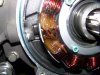
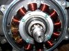
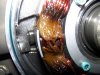
the new belt came in today. i'll probably just belt it up, check the swingarm as best i can, and button it down. incidentally, i took the stator rotor off today to take a look at the stator while i had access to it. i had no reason to suspect any problem. no funky smell. i've included a pic of the stator. there's some greasy lookin material between three of the coils. i guess its just some kinda insulator where the wires come in the back? anybody seen this? should i be worried?
thanks again, everybody.
your comments about alignment tells me that lateral deflection IS possible at the swingarm. so even though the swingarm bearings are pressed into the swingarm (suggesting a rigid assembly with no possibility for lateral deflection unless a bearing is broken), that bearing must not be fixed in the metal of the swingarm tube. the rubber bushing must hold the bearing and its the rubber bushing that allows lateral deflection. does this sound right? if so, then what you're saying about centering the swingarm shaft makes sense to me.
i took a close look at my front engine mount. one of the bolts that connects the front engine bracket to the frame was loose. everything else, including the adjuster linkage was tight. rubber looked good on the damper. i wanted to see what the position of the bracket bolts was in the slot so i took out one of these bolts. it was positioned all the way to the left in the slot. i have to say that makes me suspicious about my original guess. if the front of the engine/tranny is pulled to the left, and this causes an angle at the tranny/swingarm connection, then the outside edge of the tranny pulley is a little closer to the rear wheel pulley than the inside edge. if i'm right, this could explain the outside edge wear on the drivebelt. finding the engine bracket bolt located all the way to the left in the slot doesn't make this true, but it sure makes me suspicious. at this point, i'm tempted to turn it over to someone who does harley chassis alignments all day and has the equipment and expertise, but i gotta tell you, i don't have confidence that i know who that person is.
the new belt came in today. i'll probably just belt it up, check the swingarm as best i can, and button it down. incidentally, i took the stator rotor off today to take a look at the stator while i had access to it. i had no reason to suspect any problem. no funky smell. i've included a pic of the stator. there's some greasy lookin material between three of the coils. i guess its just some kinda insulator where the wires come in the back? anybody seen this? should i be worried?
thanks again, everybody.
Attachments
dolt
Well-Known Member
I have included a link to the power train alignment procedure/instructions using the Jim's tool. Not suggesting that you buy the tool but thought that a read of the instructions on how to use the tool would clarify the issue of power train alignment.
http://jimsusa.com/tech/instructions/900/964-IS.PDF
I use lasers and digital levels and follow the Glide Pro procedure; the levels are also inclinometers or angle gauge. The Glide Pro alignment method all depends on the accuracy of the first step, leveling the bike and getting the neck exactly vertical. They use the 2 frame rails under the seat to level the bike hopefully getting the bike perfectly vertical. The problem is these rails are not exactly 90 degrees to the neck on some bikes. You need a second reference to level the bike. Also you can do a double check using the lasers, in addition to shooting the lasers that are on the front and rear rotors at each other and the floor you can turn the lasers on the front rotors up at an angle to allow measuring in the frame backbone somewhere above the engine, this is done with the front rotors reading 90 degrees or vertical. This double checks the "levelness" of the bike and helps to verify that the neck is vertical and the front end/wheel is pointed straight ahead.
Sounds anal but if one is going to the trouble to align the drive train, one might as well get the tools (I think I have about $100 in levels and lasers from Sears) and do it right. If not, one will never know if the power train is aligned with the chassis.:s
I wouldn't worry about what you see at the stator.
J
Jack Klarich
Guest
Harley Davidson Forums
Look here to test your stator:s
Look here to test your stator:s
oldscoolz
Member
thanks jack, dolt, brian, others. here's what i think is correct about the 2002 flhri drivetrain, based on comments, looking at exploded schematics from ronnie's, jake's glidepro videos, and other threads.
the engine, tranny, swingarm, and rear wheel are basically one solid unit in terms of lateral movement (like you said, Brain). that unit has four connection points to the chassis. the front motor mount, the top motor mount, the ends of the swingarm, and the rear shocks. there shouldn't be any adjustment that can change the lateral angle between the tranny and the swingarm. the swingarm bearings are pressed into the swingarm tube and have metal spacers on both sides of each bearing and then a large nonmetalic spacer up against the rear fork bracket that the ends of the swingarm sit in. somebody correct me if i'm wrong here. older models didn't have the bearings and that was a problem because of slop caused by rubber bushings.
changing the lateral axis of the drivetrain by adjusting the front motor mount won't change the angle between the tranny pulley and the rear wheel pulley unless there's abnormal play in the swingarm, and that would most likely be caused by a shot swingarm bearing.
adjusting the front motor mount is done to change the angle of the rear tire in relation to the front tire. and that can be accomplished because there shouldn't be any lateral play in the engine/tranny/swingarm unit. (but it does mean that you're pushing the ends of the swingarm forward or backward in the rear fork brackets to achieve that change in the angle of the rear wheel.)
the only way i can think of to change the angle between the tranny pulley and the rear wheel pulley is to change the angle of the rear wheel axle. man, wish it didn't have that axle cam. that is a funky setup. i may play around with ideas for drilling and tapping the end of the right side of the swingarm to install an adjusting screw for positioning the right side of the axle.
dolt, i'm back to you. pulleys are parallel but offset? is this the cause of the abnormal belt wear? my rear wheel sits to the left side of wheel well, like your before you changed it. how do you move the wheel to the center and still have the brake caliper and rotor (and beltguard) aligned properly?
bottom line. i'll put the new belt on. wait for the weather to get out and ride. recheck my wheel alignment. maybe replace and readjust the front motor mount. and then see how the bike tracks and how the belt wears
have put the new tranny pulley on (my main objective). seals replaced. still have to pull and replace the tranny shifter seal. no plans to pull the stator.
thanks everybody.
TQ did a write up on the axle cam setup and what he did to improve it.
Adjuster cam on baggers with this system - Harley Davidson Forums - HDTimeline.com
Adjuster cam on baggers with this system - Harley Davidson Forums - HDTimeline.com
If the pulleys are offset then perhaps replacing the front pulley spacer with a different size spacer will move the gearbox pulley further from the gearbox or closer to the gearbox depending on the size of spacer (provided tc are similar to evo bikes in this respect)
On my bikes not any touring the brake calliper pulley etc are all mounted to the parts that would move if adjustment was made to the drive train their relationship to each other would stay the same but the space they use under the fender may be different
Brian
On my bikes not any touring the brake calliper pulley etc are all mounted to the parts that would move if adjustment was made to the drive train their relationship to each other would stay the same but the space they use under the fender may be different
Brian
oldscoolz
Member
bodeen, good reminder on tq's thread. i remember it.
brian, i'll have to put a line on the pulleys to see if they're staggered (parallel but not in line). by bet is that this is the case and maybe a spacer will work. that tranny pulley is sandwiched between the tranny and the primary chain case. i don't think there's any free space on that shaft for any real moves with a spacer, but maybe.
brian, i'll have to put a line on the pulleys to see if they're staggered (parallel but not in line). by bet is that this is the case and maybe a spacer will work. that tranny pulley is sandwiched between the tranny and the primary chain case. i don't think there's any free space on that shaft for any real moves with a spacer, but maybe.
03ultra45385
Active Member
If memory serves me right the front pulley has no flaange as the rear does. newer bikes with narrower belts use the same front pulley but a narrower rear pulley. that being said the front pulley is wider than all the different rear pulleys. The rear pulleys have the inside and outside flanges that keep the belt somewhere between those flanges. If your belt is running tight against the left or outer flange the axle/cam on the right side of the wheel is probably been pulled away from the mating surface for the cam. This usually happens when tightening the axel nut from the rear of the bike while tryiny to hold the axle from turning. It worked better for me the last time i changed the rear tire if one person kept the axel from turning while i tightened the nut while pulling on the ratchet toward the front of the bike which helped to pull the axle/cam tight against its seat. The drive belt should have close to the same gap on both sides of the belt in the rear pulley. Best checked by driving the bike forward and simply stopping the bike and looking at the gaps at the rear pulley. If you find that the belt is running against the right/inner flange you may want to replace the cam on the right side or fit some shim stock between the flats of the axle and the cam or using a feeler between the cam and its mating tab on the swing arm to adjust the alignment. Once you have the belt aligned you can use the string method to check the front/rear wheel alignment. then using a digital level you can check the vertical alignment of the wheels by measuring the angle of both wheels while the string is still checking that they are pointed in the same direction. I don't know how to simplify this any shorter. I hope this helps.